17A. Remove two small screws as shown:
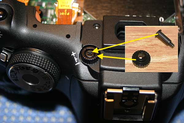
17B. Remove the diopter adjustment screw and cam:
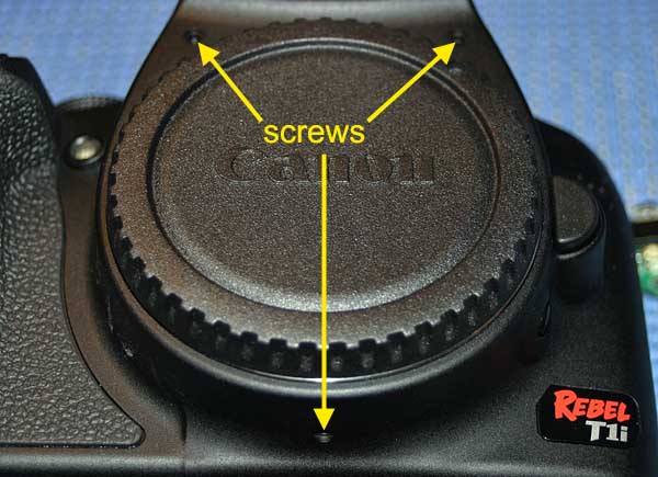
17C. Remove three screws as shown and remove the front camera cover. The top two screws are slightly larger than the bottom screw.
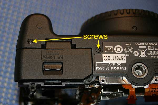
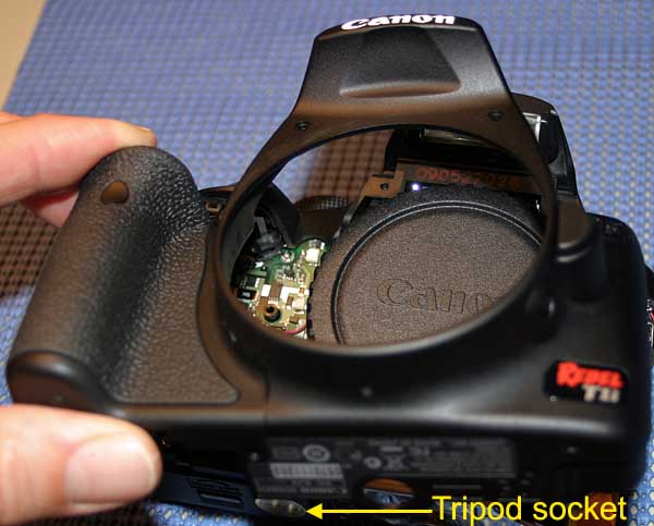
17D. Remove two screws on bottom of camera as shown:
17E. Lift the camera bottom plastic up and over the metal tripod socket and push the front camera plastic part off:
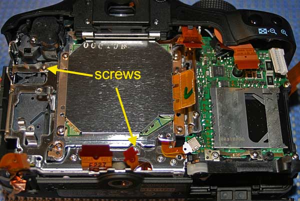
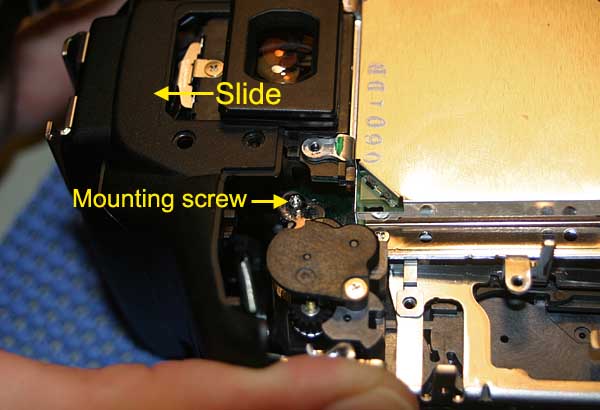
17F. The top panel can now be slid up just enough to allow access to the top CMOS assembly Torx head screw:
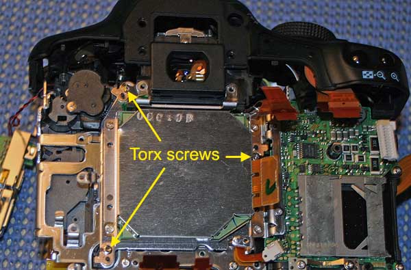
17G. The CMOS assembly unit is held in place with three Torx head screws that are also used for adjusting focus and tilt. These three screws may be fully seated or may not be and they need to be returned to their original position later in order to maintain accurate focus.
One way to do this is to place a mark on each screw head and note or mark its position. Turn each screw inward while noting how many turns until the screw is fully seated. During re-assembly you will need to fully seat the screw and use the mark as a guide for loosening the screw the correct number of turns for each screw.
Another way to do this is to etch a thin line on the black plastic pin that sticks up through the shim of each mounting screw. This etched line can then be used as a quide during re-assembly.
Another way is to measure the length of the black plastic pin that sticks up through the shim of each mounting screw and a make a guide that can be used during re-assembly.
Note: You may want to do all three methods above to improve the accuracy of returning the screws to their original position.
Clean the black adhesive from each of the three mounting screws with a razor knife and remove the three screws using a Torx T-7 driver. Be careful when doing this since the mounting screws are spring loaded and there are thin shims on each of the screws. The number and thickness of these shims is important to restoring the camera for sharp focus across the field of view, so be careful when removing the shims and note their location so that they are returned to their original positions. When the Torx mounting screws are removed the springs will also be loose so be sure they don't fall out of the camera.
Brent
Maynard reports that a Torx T7 was not the correct size needed
to remove his CMOS assembly screws, but a T6 size worked instead.
He notes: "Canon could be using different sizes."
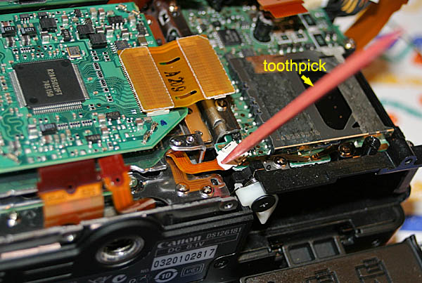
17F. Disconnect ribbon cable from small white connector as shown. It is a slide type connector. Use a toothpick in the ribbon cable hole to wiggle it out gently.
17G. The next step is to remove the CMOS imaging chip/circuit board assembly. Be careful when removing it because there will be an exposed filter on the back side. Move the small ribbon cable in the photo above behind the metal tab, so it does not get hung up on the metal tab when removing the assembly. The assembly needs to clear small black pins first to become totally free. Here is the assembly removed.
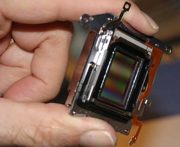
Keep parts that you remove in plastic Glad food containers to keep dust free. Now continue to the next page for steps on replacing the IR Cut filter of this CMOS imaging chip/circuit board assembly.