(For previous Steps 1 through 6 click HERE.)
7. Open the camera back from the top end by prying it with your fingernails so that it hinges at the bottom where two ribbon cables are connected.
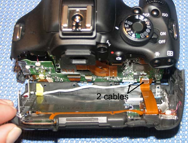
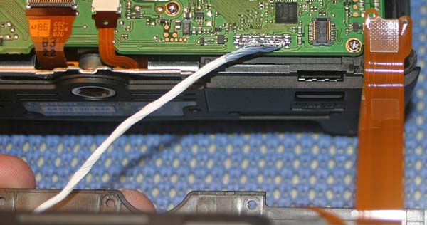
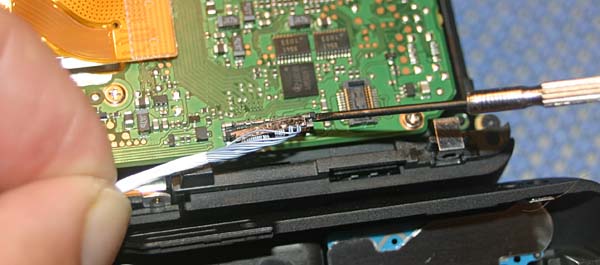
8. The two cables connecting the camera back have pop off connectors. For both connectors, pry up the end of the connectors to loosen them for removal. The orange ribbon cable is easy to remove. Be careful when removing the white cable from its connector; I used a small flat head driver to gently pry the metal ends upward. Do not force the white cable connection. It should disconnect easily. Avoid contacting the circuit board near the connector. When disconnected, place the back of the camera in a sealed container.
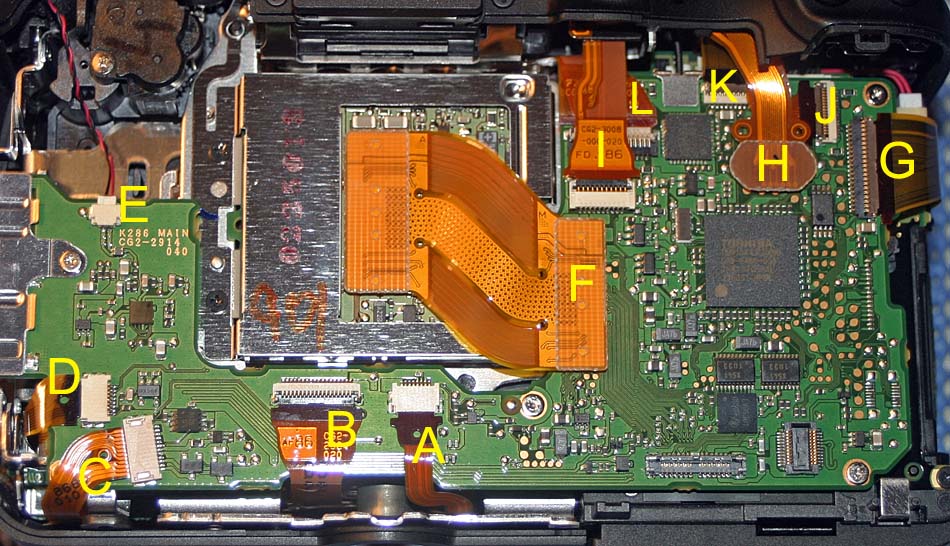
9. In the photo below, the ribbon cable connectors are labeled "A" through "L" for reference. We will disconnect all of these ribbon cables in the next steps. It is important to note how far each cable is inserted in its connector for reassembly later. You may want to mark each cable with a fine tip black marking pen before removal as a visual aid for judging how far the cables need to be inserted.
A. This is a "slider" type of ribbon cable connector, not a "hinged" type. Insert a toothpick in the small hole in the ribbon cable and wiggle the cable gently from side to side as you apply pressure away from the connector to pull the ribbon cable out of the connector:
B. This is a hinged type connector. Use
a small flat head jeweler's driver to flip up the dark part of
the connector which is hinged so that it moves up and away from
the ribbon cable allowing the ribbon cable to be removed. Remove
ribbon cable with rubber tipped flat head tweezers: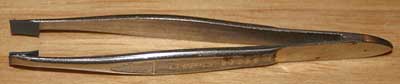
C. This is a "slider" type of ribbon cable connector. Insert a toothpick in the small hole in the ribbon cable and wiggle the cable gently from side to side as you apply pressure away from the connector to pull the ribbon cable out of the connector.
D. This is a "slider" type of ribbon cable connector. Remove ribbon cable with rubber tipped flat head tweezers.
E. This is a "slider" type of ribbon cable connector. Use the edge of a razor knife to loosen and remove ribbon cable with tweezers.
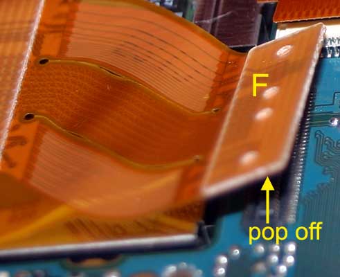
F. This is a "pop off" (plug type) connector. Lift it off with a tooth pick or your fingernail:
G, I, J, K & L. These are hinged type connectors. Use a small flat head jeweler's driver to flip up the dark part of the connector which is hinged so that it moves up and away from the ribbon cable allowing the ribbon cable to be removed. Remove ribbon cable with rubber tipped flat head tweezers.
H. This is a "pop off" (plug type) connector. Lift it off with a tooth pick or your fingernail.
All the ribbon cables "A" through "L" have now been disconnected:
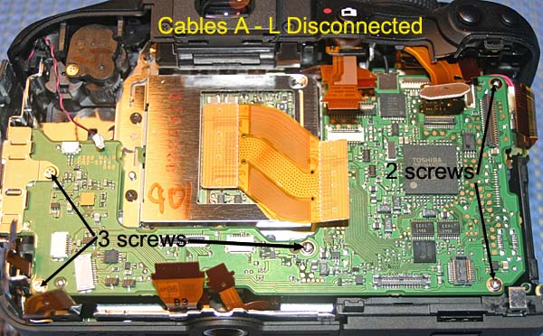
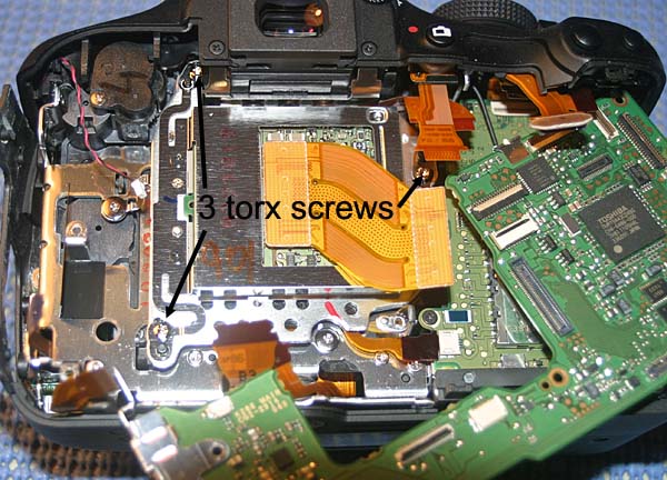
10. Remove three small screws and two long screws as shown in the above photo.
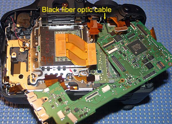
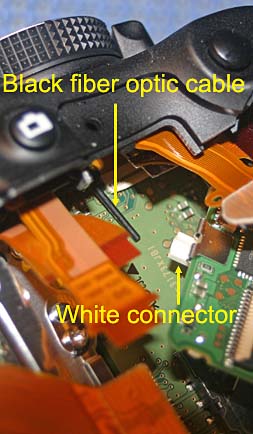
11. The circuit board will now be shifted to get access to the imaging sensor assembly. Move the circuit board away from the sensor assembly and to the right as shown below. The circuit board remains connected in the upper right corner by a cable that remains connected. The black fiber optic cable may become disconnected from its white connector on the circuit board.
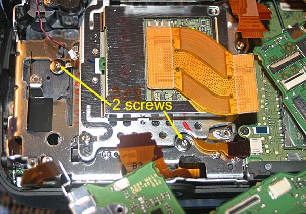
12. Remove two screws on grounding strap as shown below.
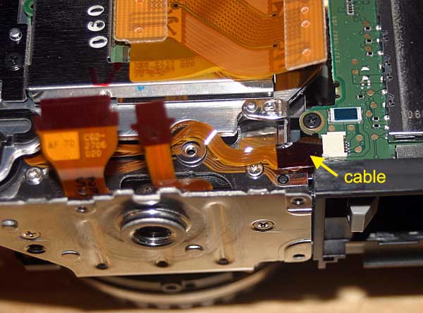
13. Remove small ribbon cable from its white connector by pulling it using rubber tipped flat head tweezers:
14. The CMOS assembly unit is held in place with three Torx head screws that are also used for adjusting focus and tilt. These three screws need to be returned to their original position later in order to maintain accurate focus.
One way to do this is to place a mark on each screw head and note or mark its position. Turn each screw inward while noting how many turns until the screw is fully seated. During re-assembly you will need to fully seat the screw and use the mark as a guide for loosening the screw the correct number of turns for each screw.
Another way to do this is to etch a thin line on the black plastic pin that sticks up through the shim of each mounting screw. This etched line can then be used as a guide during re-assembly.
Another way is to measure the length of the black plastic pin that sticks up through the shim of each mounting screw and a make a guide that can be used during re-assembly.
Note: You may want to do all three methods above to improve the accuracy of returning the screws to their original position. For a Full Spectrum modification only, using an Astronomik MC Clear Glass DSLR replacement, the screws need to be turned in an additional 1/12th turn from the original position after modification.
Clean the black or red adhesive from each of the three mounting screws with a razor knife and remove the three screws using a Torx T-7 driver. Be careful when doing this since the mounting screws are spring loaded. When the Torx mounting screws are removed the springs will be loose so be sure they don't fall out of the camera.
15. The next step is to remove the CMOS imaging chip/circuit board assembly. Be careful when removing it because there will be an exposed filter on the back side. The assembly needs to clear small black pins first to become totally free. Here is the assembly removed:
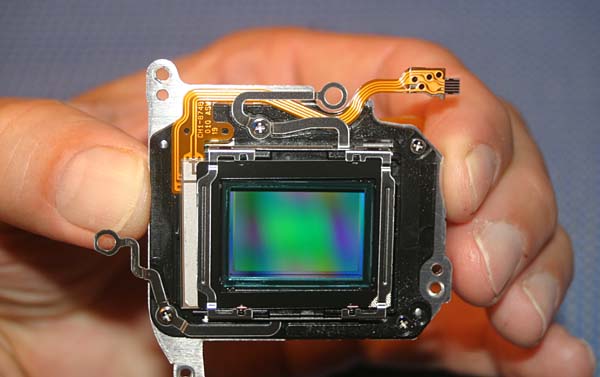
Continue with steps to remove filters from sensor