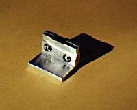
 Cold Plate
for CCD
Cold Plate
for CCD5.Cold Plate
for CCD
For all thermal surface connections I used Radio shack heat sink compound (RS# 276-1372 - $1.99). This paste ranks best for heat transfer by reviewers of the different thermal pastes. A flat area is filed and sanded for seating the CCD chip
6. 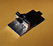 CCD on Cold
Plate
CCD on Cold
Plate
Here the CCD is placed on the cold plate. An 8-pin socket was cut in half and each half (4 pins) was used for the connections to the CCD chip.
7. 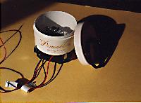 (click for larger image) Cosmetic Case & Peltier
The CCD/cold plate assembly was mounted in the cosmetic jar on the peltier. Any openings in the cosmetic jar from cable holes were filled with silicone sealant.
8. 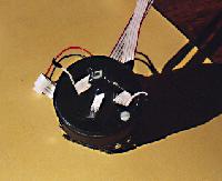 (click for larger image) Cabling the CCD Chip
My first installation as shown above used 26 gauge ribbon cable to connect the CCD chip to the motherboard. The cable was 5.5 inches long and the CCD did not work with this length cable. For an analysis of different cable lengths and types tried click here. The final working camera used single 22 gauge conductors of 2.0 inches length. For anyone that is planning to build a cooled greyscale, I recommend that the unit be designed to keep the CCD leads to the circuit board as short as possible.
9. 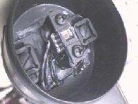 (click for larger image) Closeup of CCD on Peltier/Cold
Plate
(click for larger image) Closeup of CCD on Peltier/Cold
Plate
The CCD chip was held firm to the cold plate by a thin plastic strip with a square hole to expose the CCD imaging area. Two small screws hold the plastic strip onto the aluminum cold plate. Two nylon bolts and square plastic washers hold the cold plate firmly onto the peltier.
...Continued on Page 3 - Click Here