
Opening the camera will void your Canon warranty and you may ruin your camera. Proceed at your own risk; I am not responsible for any damage to your camera or injury to yourself. The camera contains a high voltage capacitor that stores lethal energy for the camera flash. The flash capacitor maintains its charge for a long time even after removing the battery and this charge can cause dangerous injury or even potentially fatal electrical shock. These instructions detail how I as an electrical engineer do camera modifications. If you attempt to modify your own camera it is at your own risk and I am not responsible for any damage or injury. I am an electrical engineer and have done other imager modifications including building a peltier cooled webam ; the Steve Chambers long exposure modification (SC-1) to the Philips Vesta Webcam; modified Logitech Fusion , Pro 9000 and Microsoft Lifecam Cinema HD webcams and modified Canon 300D. I have also modified many hundreds of DSLR cameras. The most difficult part of the modification are the many ribbon (flat) cable connections involved and removal of the IR cut filter from its holder above the CMOS imaging chip. If you have a problem with your camera after the modification, it would most likely be due to a ribbon cable connection not being fully seated in its connector.
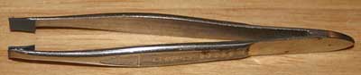
The modification of the 450D, 1000D, 500D, 550D, 600D, 650D, 700D, 1100D &1200D is easier than that of the 300D from the standpoint that there is no de-soldering or soldering required. The tools needed are very simple as shown above. From left to right starting at the top of the photo: silicone glue, #000 size philips screwdriver (#Craftsman #45726), jewelers screwdriver set bought at the $1 store, exacto razor knife, magnifying glass, microfiber lens cleaning cloth, nitrile gloves (not shown) and toothpicks. The nitrile gloves are for handling the bare replacement filter. For the T5 (1200D) modification, you will also need a Torx T-7 driver. For some models, rubber tipped flat head tweezers are needed for removing and inserting ribbon cables. I made a pair by using rubber shrink wrap on metal flat head tweezers.
...Before beginning, you may want to take a few "before modification" photos to later check how focus and clarity of image is affected by the modification. Although only needed in a very dry environment, you may want to wear a grounded wrist strap for static protection while handling electrical components.
For the many small screws removed, you can tape them to a piece of paper with notes on step number and size, location and assembly step, in the order of removal.
You can place the circuit board removed in Glad plastic food containers to keep dust-free.
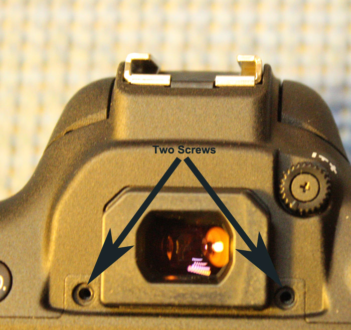
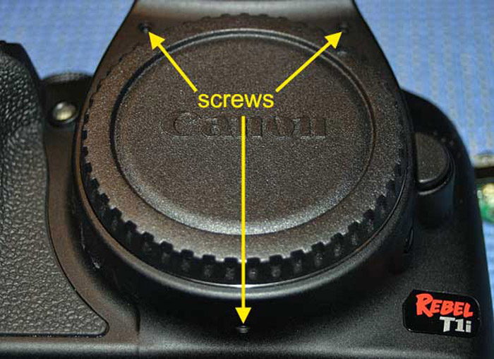
1. Remove the lens and place the front cover on the camera body to keep dust out. Remove battery, SD card and viewfinder cap. The viewfinder cap slides up. There will be two screws under the cap that need to be removed.
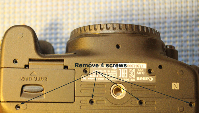
2. Remove four screws from bottom of camera as shown. All screws are the same size:
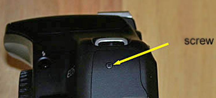
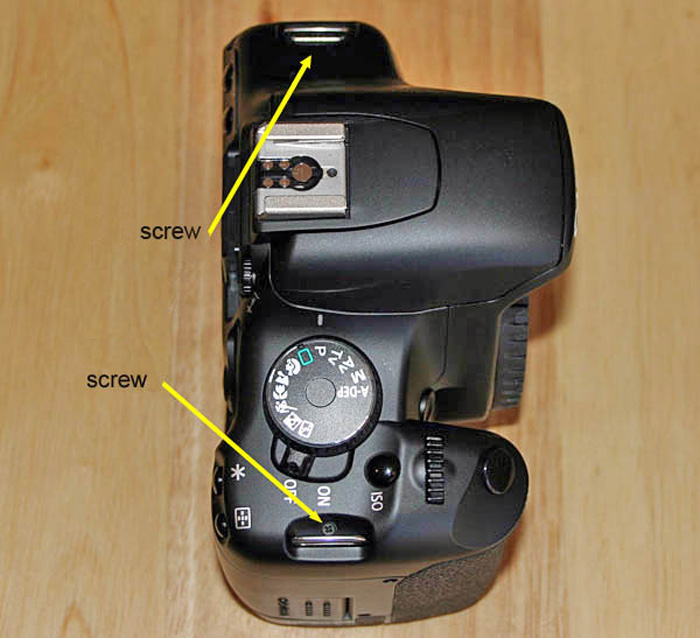
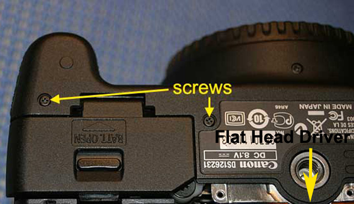
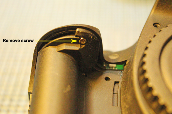
3. Remove one screw from side of camera above port:
4. Remove two screws from other side of camera. Both screws are the same size. Image below is from 450D model:
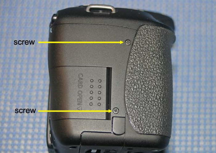
5. Remove screws located near neck strap mounts. Both screws are the same size. Image below is from 450D model:
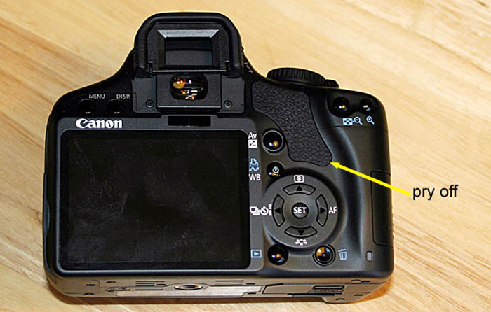
6. Remove rubber piece as shown below. It is adhesive backed and can be easily removed by prying one corner up with an exacto razor knife and lifting the rest of the piece off with your fingers. The rubber piece needs to come off to allow the plastic camera body to come apart. It can be easily put back on after re-assembly. Image of the 450D is shown below and the T5 piece is much narrower:
7. Lift up the rubber port cover and remove two screws, and remove port cover. Image of the 500D model is shown below:
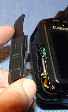
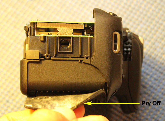
8. Carefully pry case apart starting from the bottom side of the camera. Be careful because the camera back is attached by two ribbon cables as shown below. Disconnect both ribbon cables before removing the camera back:
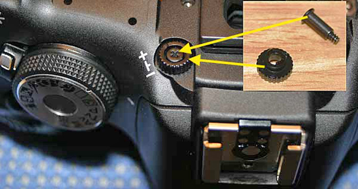
9. Remove diopter screw and diopter cam as shown below:
10. Remove three screws from front of camera as shown (photo of T1i shown below):
11. Remove two screws on bottom of camera near the battery compartment (photo of T1i shown below):
12. Use a small flat driver to lift one corner of the rubber grippy material on the hand grip nd peel the rubber grippy material off the camera:
13. Remove one screw under black grippy material as shown below:
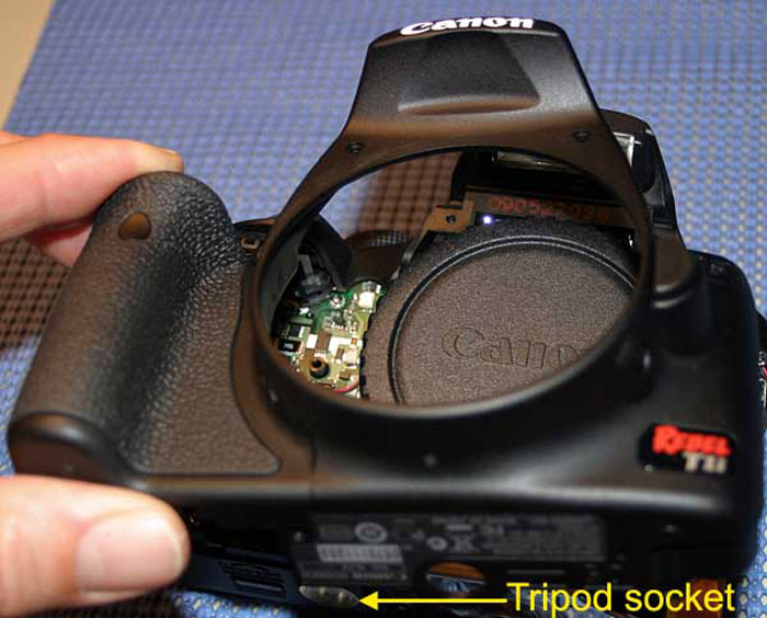
14. Place a flat head driver under the black plastic circle around the tripod socket and lift the plastic piece over and above the tripod socket as the location of the arrow in the image shown in Step 11. Lift the camera bottom plastic housing up and over the metal tripod socket and push the front camera plastic housing part off the body (photo of T1i shown below):
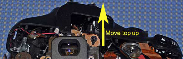
15. Move top of camera upward a little:
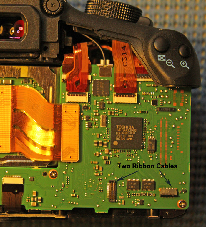
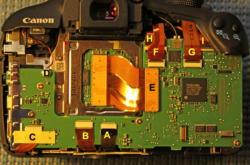
16. T5 Mainboard with ribbon cables labeled:
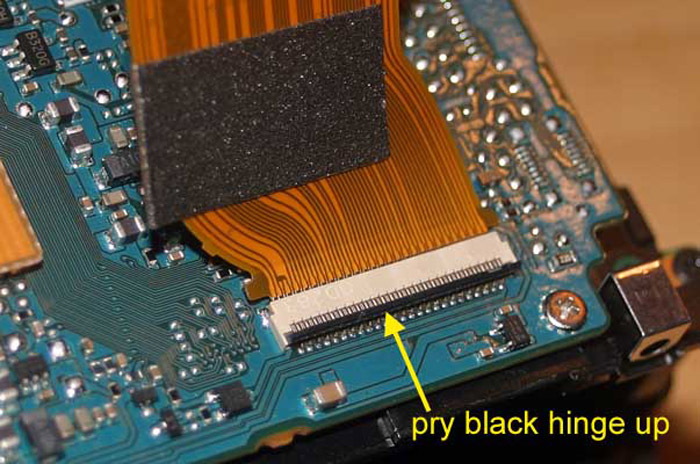
Here is a photo of a typical "hinged type" connector that shows how the connector is flipped up to allow removal of the ribbon cable. To install a ribbon cable, the cable would be placed into position and the hinge snapped down to hold the cable in place.
For the T5 model these are the types of connectors as labeled in Step 16:
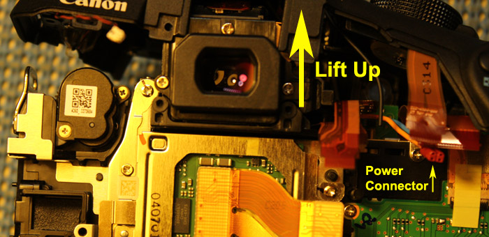
17. Wiggle up the top of the camera as shown below:
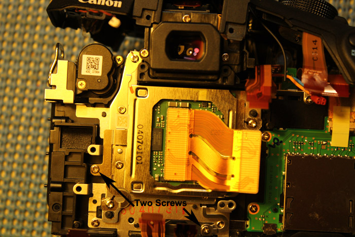
18. Remove two ground screws as shown below:
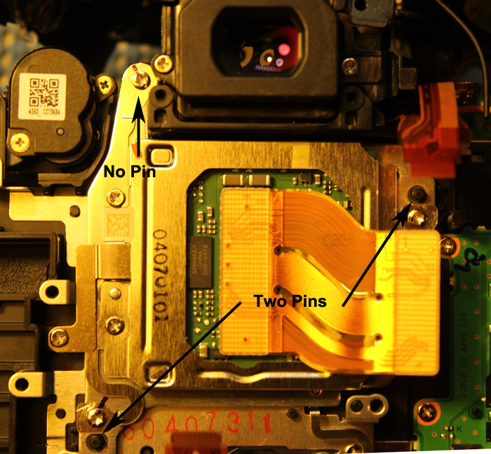
19. Usually the sensor has three plastic pins near the three sensor adjustment screws. The T5 model only has two pins as shown below. The first thing you should do is use a ultrafine point black sharpie to mark the original positions of the sensor adjustment screws as shown:
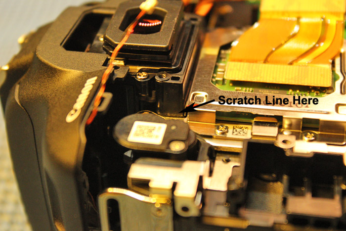
20. For the sensor screw without a black pin you can mark the original position by two methods shown below:
Scratch a line in the black plastic near the sensor screw as shown:
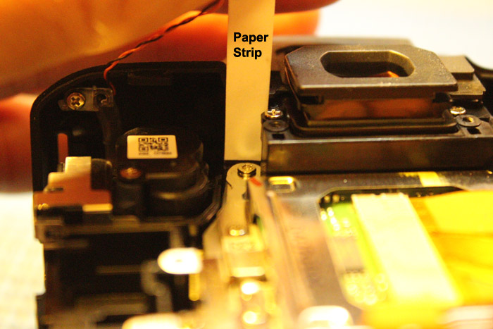
Make a paper measuring strip using a business card, use a black sharpie to measure how high the metal frame around the sensor screw is. There is a part behind and close to the sensor screw to use the measuring strip on as shown below:
Continue Here to the next modification steps.