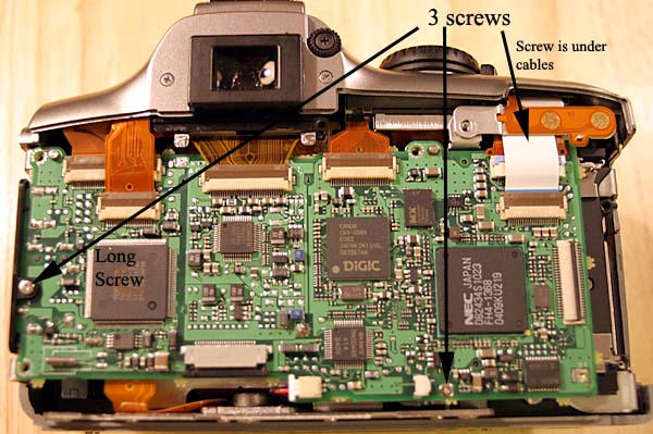
19. Remove three screws shown below. One screw is for removing the port cover which is longer than the other screws.
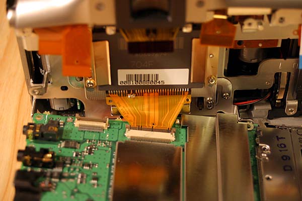
20. With all six ribbons disconnected from the top of the board, release the smaller of two brown and tan hinged type connectors at the bottom of the board. Remove the ribbon cable using a toothpick in the ribbon hole.
21. Lift the top of the board off the two metal pins slightly and shift the top of the board to the left to free the upper right hand corner. Now lift the top of the board away from the camera, it will still be connected by one ribbon cable at the bottom. Release the ribbon cable hinged connector and remove the cable.
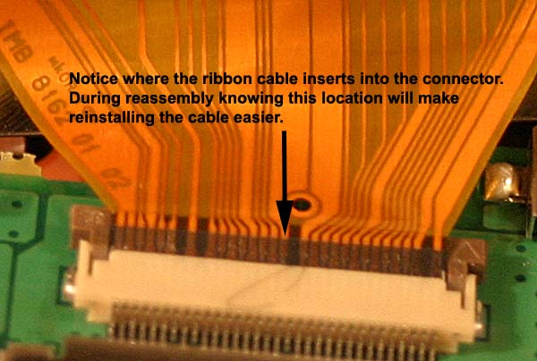
Close-up of above ribbon connector. This connector is different from the others; the ribbon cable inserts on top of the hinged part, not beneath the connector.
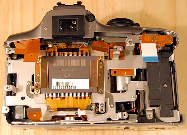
22. Disconnect power connector at bottom of board. It is a white connector with black and red wires. I used a razor knife to pry the connector open. This photo shows the power connector disconnected and the board removed:
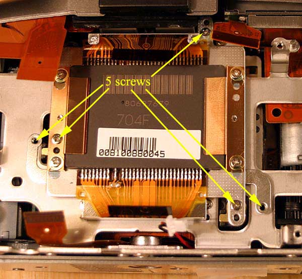
23. Remove the CMOS Imager assembly by removing these five screws. Two screws for the curved grounding straps are shorter than the three screws that mount the CMOS imaging assembly to plastic camera posts. On these three camera posts will be small copper metal spacers, be careful that they don't fall off. In the next step, we will be making small .1mm spacers to add to the copper metal spacers for achieving focus. Lift CMOS assembly out of camera and put camera body in a sealed container to keep dust free.
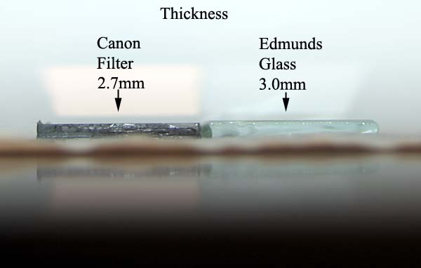
24. The three .1mm spacers needed can be made out of 3M Transparency film (#CG3460). The film is 4.5 mils thick which is .119mm, close enough to the needed .1mm to achieve the original focus point. Here is how this was calculated:
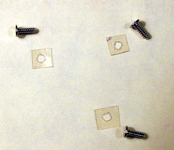
Cut the three spacers out of the transparency film to a size of about 4mm by 4mm. Cut hole in the center of each with an exacto knife. The hole should be large enough for the CMOS assembly mounting screws to fit through.
This tip is from Dan McCauley: For his modification he used spacers made from a standard feeler gauge he bought from Pep Boys for $1.99. It had a leaf exactly 0.1mm wide. He taped the leaf to a piece of wood, drilled a hole the diameter of the screws and cut it with scissors.
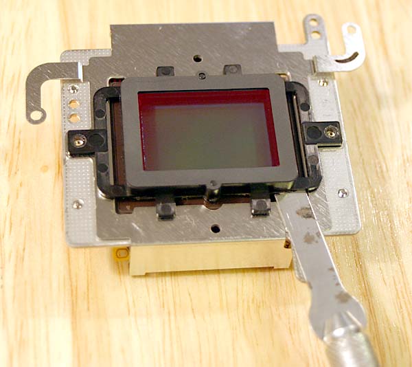
25. Remove two screws from black plastic filter frame:
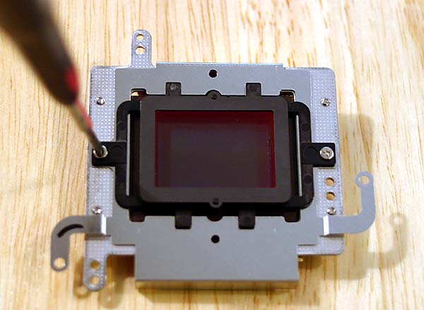
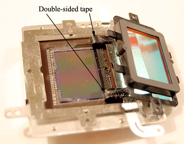
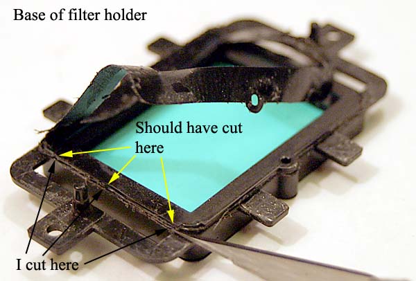
26. The black plastic filter frame is still attached to the front glass of the CMOS chip by thin double-sided tape. I used a few different types of exacto razor blades, including flat chisel types, to cut around the frame between the bottom of the black plastic frame and the top of the double-sided tape. I worked on cutting this for over an hour which resulted in the plastic filter just pulling away from the CMOS chip. I learned that the area I had been cutting was still the plastic frame and so the tape becoming undone was a result of vibrations and prying from my cutting attempts. Here is a photo showing where I was cutting:
I should have been cutting a little lower (very small distance - see photo below) to get into the double-sided tape, but I think this would have been a little riskier to do since I would have been cutting closer to the CMOS imaging chip cover glass. I would recommend that instead of cutting, a blade such as I used above, or even a wider blade, be used to gently pry the black plastic frame up, going around the perimeter a few times until the tape loosens from the CMOS chip. This was the hardest part of the modification procedure. The double sided tape peeled off the CMOS chip with some slight pressure as a complete unit without breaking and I was able to reuse it.
This
comment is from Chris Venter: "I was surprised how easily
the filter holder came away from the chip. I just put a very thin
blade underneath and gently applied upward presure. The whole
assembly just peeled slowly away from the double sided tape and
left the tape neatly in place around the chip."
Remove double-sided foam tape from black plastic filter holder and put between wax paper for later use.
Continued on Next Page (Page 5) - Disassembly of Camera Continued