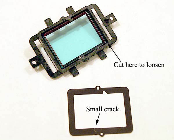
27. The front of the IR filter window has a thin black gasket. It is attached with one or two small drops of glue. Trim it off with an exacto knife but be careful not to scratch the IR filter if you want to reuse it someday. My gasket had a small crack which I repaired with a black magic marker and ultra-flat paint. The gasket is used as a shield to prohibit glare from the filter's edge.
NOTE: At this point I studied the camera for possible peltier cooling, both directly and indirectly and made plans. The plans are in PART 2.
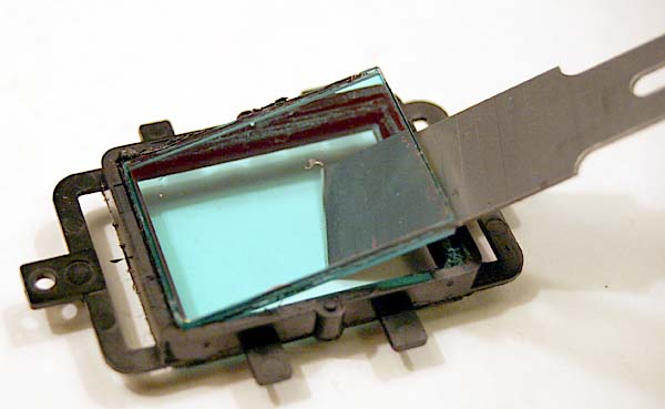
28. The Canon IR filter glass is glued in the black plastic filter holder. Cut the glue around the glass to work it loose and free it with a razor knife.
Pry glass up with broad blade (chisel type) exacto razor knife:
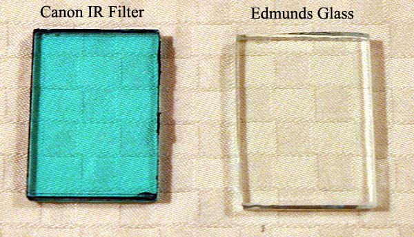
29. If needed, sand edges of the new Edmunds clear glass under cold running water using #220 wet-dry sandpaper. The glass I cut was a little too big because the break was at an angle and the angle needed to be flattened by sanding it down. In addition, I had to enlarge the inside diameter of the black plastic filter holder with an exacto knife; this was easy to do. Clean the cover glass with a mixture of distilled water and alcohol and dry it with microfiber cleaning cloth. Reinstall it in the filter holder. I used "Weldit" all purpose adhesive (glue) by Devcon in the corners of the glass to hold it in place. Put a drop of glue in each corner of the holder and then place the glass in the holder and press down evenly to insure that the glass is sitting squarely in the holder.
30. Reinstall double-sided tape onto back of the filter holder. Make sure the CMOS imaging chip is clear of dust. I just used a blower bulb. Assemble the CMOS chip, its metal shielding and filter holder and secure with two screws. Attach the thin black gasket to the filter holder with a few drops of glue, making sure that is is flat and is seated flushly on the filter holder. Be careful not to get any glue on the glass window.
Note: I updated Step 30 after Jaime Alemany reported that the thin black gasket needs to be mounted on the black plastic filter holder very flush with the holder. His gasket was not flush and it resulted in damage being done to his shutter. He was able to repair the shutter and his camera is working well. No one else reported having this problem.
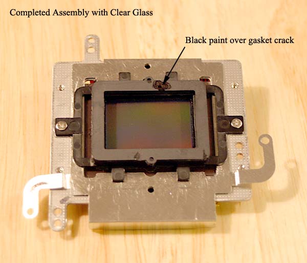
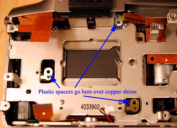
31. Place the three square transparency film spacers made in Step 24 on the three posts that support the CMOS assembly as labeled in photo below. I noticed that my camera had two brass spacers on the two right side posts and only one spacer on the left post. I think Canon uses these spacers to "level" the CMOS chip so that focus is even across the field. Installing the three transparency film spacers moves the CMOS chip back evenly the distance needed to maintain autofocus because of the difference between the filter glass and replacement clear glass thickness (see Step 24 for an explanation).
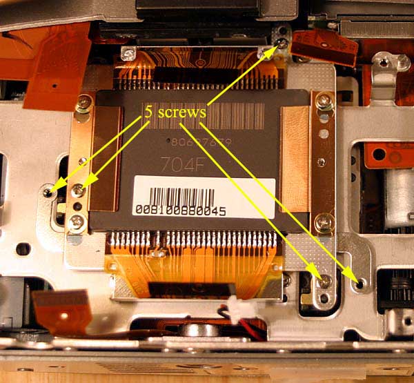
Install the three long screws on the CMOS support points with spacers and two short screws for the grounding straps:
Continued on Next Page (Page 6) - Disassembly of Camera Continued